Flagship / MOTOR DRIVE

Industrial Motor
Drive Solutions

From power device to complete system, we deliver kitting stage by stage — rectifier, bus, inverter, gate drive, sensing, control and protection — with a production-ready set of parts at every level.

Topology / POWER PATH

The whole drive, device by device

The power path from grid to motor, plus the control loop formed by the gate drivers, sensing and the main controller.

L1L2L3EMI FilterCM chokeRectifier3-ph bridge+−DC bus ≈ 537 V+Bus capacitors3-phase inverter · IGBT / IPM / SiCUVWM3~Aux SupplyAC/DC · isolatedGate Drivers ×6Isolated · DESATSensing & FeedbackCurrent · temp · positionRsMain Controller · DSP / MCUFOC · SVPWM · dead-time compensation · fieldbus
← Scroll to pan, or tap Zoom for full screen →

The hard part of a drive is never one device — it is matching the whole chain. Bus voltage sets the device voltage class, switching frequency sets loss and cooling, sensing accuracy sets how fast the current loop can run, and drive quality decides whether the device ever reaches its datasheet numbers.

What we do is fill that chain in one go — power devices through our partner fabs' factory channels, gate drive, control and passives kitted to the system requirement, and our engineers involved in topology, thermal design and EMC.
Scope / COVERAGE

0.4kW — 630kW

  • Kitting for general purpose VFDs, servo drives and dedicated drives
  • Both induction and permanent magnet synchronous designs
  • IGBT, IPM and SiC routes chosen against cost and efficiency targets
  • Followed through from board prototype to volume ramp
From parts to product / THE CHAIN
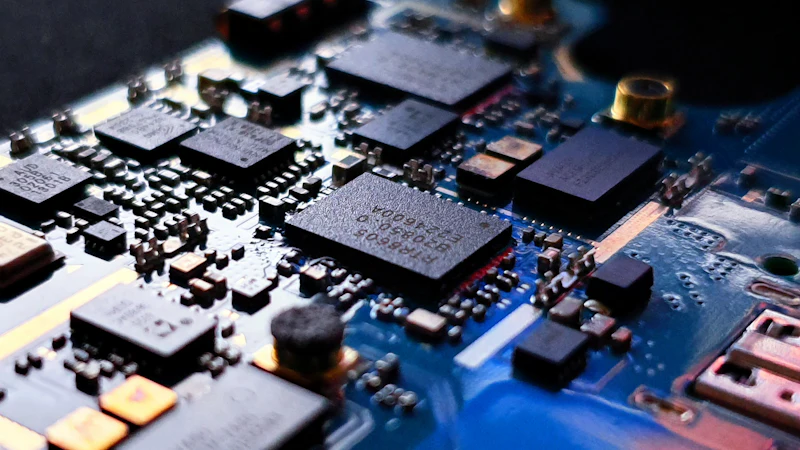
Power stage with inductors, capacitors and ICs
Power stage · magnetics, caps and drivers
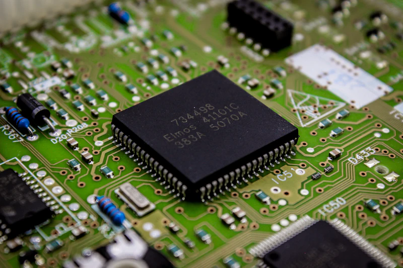
QFP controller IC on a circuit board
Control board · main MCU
AC motor in service
Load · industrial motor
Kitting list / BOM

Eight stages, each with a production-ready set of parts

Every group names the product line or partner fab behind it — click through to see the source.

01

Input & Rectifier Stage

From the grid to the rectifier output — this stage sets EMC behaviour and inrush.

  • EMI filteringCM and DM chokes, X / Y capacitors
  • Bridge rectifierThree-phase bridge modules and discrete bridges
  • Surge suppressionMOVs and NTC inrush thermistors
  • Pre-charge circuitCharging resistor with bypass contactor or thyristor
02

DC Bus

Bus support and snubbing, which directly affect device stress and system life.

  • Bus support capacitorsHigh voltage aluminium electrolytics selected on ripple current and life
  • Snubber capacitorsLow inductance film capacitors to limit turn-off spikes
  • Balancing and dischargeBalancing and bleeder resistors
  • Bus voltage sensingHigh voltage divider resistors and isolated sensing
03

Inverter Power Stage

The cost and efficiency core of the design, and the main product line of our partner fabs.

  • IGBT discretes650 V / 1200 V discretes for small and medium power
  • IGBT modulesSix-pack PIM and half-bridge modules for medium and high power
  • IPM modulesIntegrated drive and protection to shorten development
  • SiC MOSFETs and modulesFor high frequency, high efficiency designs with lower switching loss
  • Fast recovery diodesFreewheeling and rectification support
04

Gate Drive Stage

Drive quality determines whether the device ever reaches its datasheet performance.

  • Isolated gate driver ICsOptocoupler and digital isolation options
  • DESAT protectionFast soft turn-off under short circuit
  • Active Miller clampPrevents false turn-on from bridge-leg crosstalk
  • Negative turn-off and bootstrapImproves turn-off robustness and high-side supply
05

Control & Algorithms

The compute and timing foundation, from scalar control to high performance vector control.

  • DSP / high performance MCUMotor control cores and peripherals
  • Clock referenceSMD crystals and oscillators for carrier and sampling timing
  • Memory and isolated commsParameter storage, isolated RS485 / CAN
  • Human machine interfacePanel, display and keypad interface devices
06

Sensing & Feedback

The sensing chain sets the ceiling on current loop accuracy.

  • Precision sense resistorsLow drift alloy resistors in single, dual or triple shunt topologies
  • Hall current sensorsIsolated current sensing for medium and high power
  • Fluxgate sensorsHigh accuracy servo and power electronics applications
  • Temperature sensingNTC thermistors and module-integrated sensing
  • Position feedbackIncremental ABZ encoders, resolvers, absolute encoders
07

Auxiliary Supply

The most overlooked part of the system, and the one most likely to cause trouble.

  • AC/DC switching supplyAuxiliary supply taken from the DC bus
  • Isolated DC/DCPowers high-side drivers and isolated domains
  • LDOs and power managementMultiple low noise rails on the control side
08

Protection & EMC

Determines whether the system passes certification and survives in the field.

  • TVS and Zener diodesPort transient suppression and clamping
  • Metal oxide varistorsAbsorbs lightning and surge energy
  • CM chokes and Y capacitorsConducted emission control
  • Output reactorsLimits long-cable dv/dt and shaft currents
Sizing / POWER RANGE

Working back from system power to device choice

From a 0.4 kW integrated unit to a 630 kW cabinet drive.

Power rangeInput voltageDevice voltage classPower stageCurrent sensing
Power range0.4 — 2.2 kWInput voltage1-ph 220 V / 3-ph 380 VDevice voltage class650V / 1200VPower stageIPM or discrete IGBTCurrent sensingSingle shunt
Power range3.7 — 15 kWInput voltage3-ph 380 VDevice voltage class1200VPower stageSix-pack PIM moduleCurrent sensingDual shunt or Hall
Power range18.5 — 75 kWInput voltage3-ph 380 VDevice voltage class1200VPower stageHalf-bridge IGBT moduleCurrent sensingHall current sensor
Power range90 — 250 kWInput voltage3-ph 380 V / 690 VDevice voltage class1200V / 1700VPower stageParalleled high current modulesCurrent sensingHall / fluxgate
Power range280 — 630 kWInput voltage3-ph 690 VDevice voltage class1700VPower stageParalleled modules with laminated busbarCurrent sensingFluxgate sensor

These are typical engineering values. Actual selection depends on overload factor, switching frequency, ambient temperature and cooling — send us your operating conditions and we will check them.

Control / STRATEGY

From V/F to FOC, chosen by load characteristics

Control strategy sets what the drive can achieve, and also the cost of the controller and sensing chain.

01

V/F Scalar Control

For fan and pump loads with quadratic torque, the lowest cost to build and commission.

02

Open-loop Vector Control

Good low speed torque without an encoder, suited to general industrial loads.

03

Closed-loop FOC

With an encoder, delivers precise speed and torque control — the standard for servo and robot joints.

04

Direct Torque Control

Fast torque response for shock loads and highly dynamic applications.

Feedback / POSITION

Encoder and resolver interfaces

  • Incremental ABZ differential encoder interface
  • Resolver excitation and demodulation
  • Absolute encoders over EnDat / BiSS
  • Sensorless control, removing the feedback device
Fieldbus / COMMS

All mainstream industrial fieldbuses supported

Modbus RTU / TCPCANopenPROFIBUS-DPPROFINETEtherCATCC-Link
Safety / COMPLIANCE

Passes certification, survives the field

Protection strategy and standards have to land on the device at selection time — fixing it later is expensive.

Protection / MECHANISMS

Five protections covering the most common field failures

  • Overcurrent and short circuitA hardware comparator acts fast and DESAT provides soft turn-off, preventing device failure.
  • Overvoltage and undervoltageClosed-loop bus monitoring with a braking unit to bleed regenerative energy.
  • Over-temperatureModule NTC and heatsink sensing together allow temperature-based derating.
  • Phase loss and stallInput phase loss, output phase loss and stall detection protect the motor and drive.
  • Safe Torque OffSTO cuts the drive path directly to satisfy production line safety circuits.
Standards / REFERENCE

Designed and specified against industry standards

IEC 61800-5-1
Adjustable speed drives — safety: electrical, thermal and energy
IEC 61800-3
Adjustable speed drives — EMC requirements and test methods
IEC 61800-5-2
Adjustable speed drives — functional safety (STO / SS1)
GB/T 12668
Chinese national standard series for adjustable speed drives

Certification is applied for by the system builder for its target market; we supply compliant parts and the supporting documentation.

Engagement / HOW WE WORK

From filling one BOM to building the system with you

Three levels of involvement, matched to your project stage.

Component Kitting

We fill your whole BOM — from power devices to passives — under one lead time and batch control.

Design Support

We join in on topology, device selection, thermal design and EMC, turning datasheet numbers into a manufacturable design.

Joint Development

From prototype to volume ramp, bringing in factory application engineers where needed.

Industries / WHERE IT LANDS

Where motor drive solutions matter most

Open any industry for its selection notes and matching parts.

Send us your drive specification

Tell us the power range, input voltage, control method and cost target, and we will come back with a kitting proposal including part numbers, sources and lead times.