Tailored Industrial
Control Solutions
Built on years of field experience, matched to each application, and aimed at cutting cost and raising output.
Industrial Motor Drive Solutions
General purpose VFDs, servo drives and dedicated drives from 0.4 kW to 630 kW. We deliver kitting stage by stage — rectifier, bus, inverter, gate drive, sensing, control and protection — with a production-ready set of parts at every level.
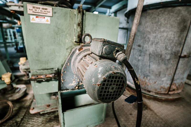
Six solution types, from a single machine to a whole line
Open any solution for detail; where a combination is needed we re-scope it against the site conditions.
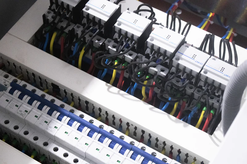
Programmable logic controller solutions for a wide range of automation scenarios
Ask about this solution- Program design and commissioning
- Hardware configuration optimisation
- System integration services
- Maintenance and training support
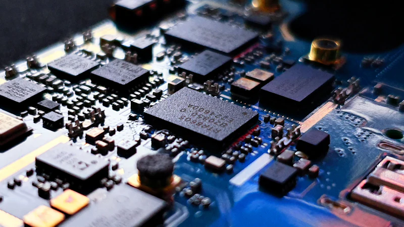
- Motor selection and matching
- Parameter tuning and optimisation
- Energy saving assessment
- Fault diagnosis services
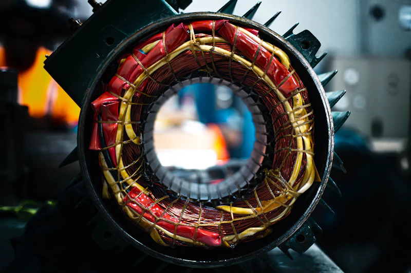
- Precision requirement analysis
- System configuration design
- Commissioning and optimisation
- Performance testing and validation
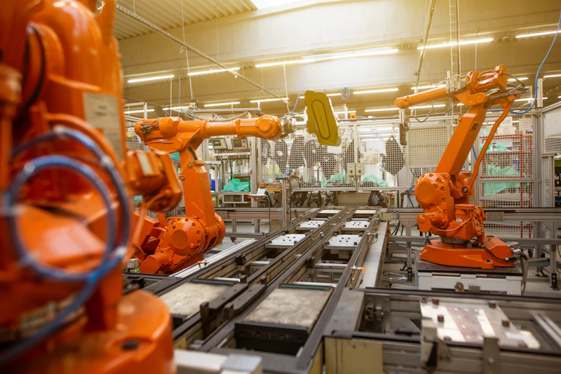
Intelligent robot control systems that raise the level of production automation
Ask about this solution- Motion control algorithms
- Sensor integration
- Safety system design
- HMI development
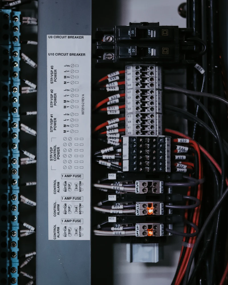
- System architecture design
- Communication protocol configuration
- Data acquisition and analysis
- Remote monitoring implementation
- In-depth requirement analysis
- Solution design and review
- Prototype development and testing
- Volume production support
Three-phase currents build a rotating field; the rotor follows
What a VFD or servo drive really does is control the amplitude, frequency and angle of that field precisely. The animation runs to scale: four electrical cycles per 10 s, two pole pairs, two rotor revolutions.
- Twelve stator slots carry U, V and W windings fed with currents 120° apart
- The resultant field rotates at electrical frequency — the blue vector
- The rotor poles follow it; mechanical speed = electrical frequency / pole pairs
- FOC splits current into flux and torque components; SVPWM synthesises the vector
PLC and VFD — the system wiring, made explicit
Align on the system structure before the design starts: what each layer does, how the signals run and where the components sit. Tap a stage below any diagram to highlight just that part.
PLC Control System Architecture
From SCADA and HMI over industrial Ethernet into the PLC rack, across the backplane bus to the I/O and communication modules, and down to sensors, actuators and drives. We can kit the components at every layer.
VFD System Configuration
A drive is never a standalone box: incoming protection, input reactor, EMI filter, brake unit, output reactor and encoder feedback each affect reliability and EMC.
A standard process that keeps projects on track
Each stage has its own deliverables and acceptance criteria.
Requirements
Understand the requirement and assess technical feasibility.
Design
Produce a detailed technical design and delivery plan.
Build
Develop, commission and test to the agreed design.
Support
Hand over and provide ongoing technical support.
Need a custom solution?
Our engineers are available for technical consultation and solution design.